RF Power Amplifier
From January to May this year, I was lucky enough to take the second running of UofT’s second year hardware design course. The class was split into groups of 3 and we each designed and built a part of the transmit and receive chains for a software defined radio. My team was tasked with making the radio frequency power amplifying stage. The basis for our power amplifier design was a common-source voltage amplifier leading into a class AB push-pull configuration power amplifier made from two power n-channel MOSFETs. Since power amplification is only required during transmission (and not when receiving signals), we designed an active-low on/off switch which would cut off power to our board completely whenever the radio is in receive mode in order to increase efficiency.
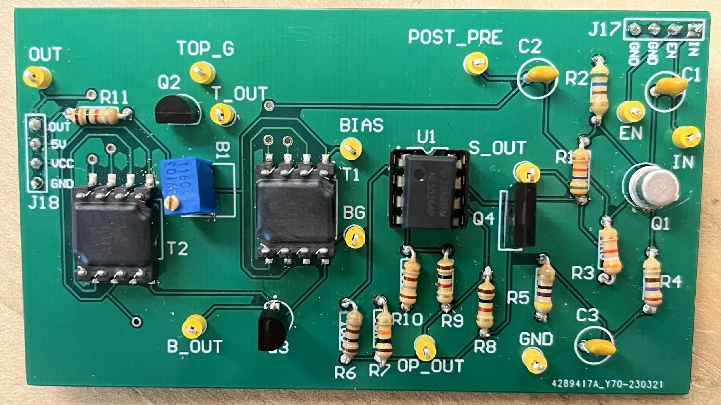
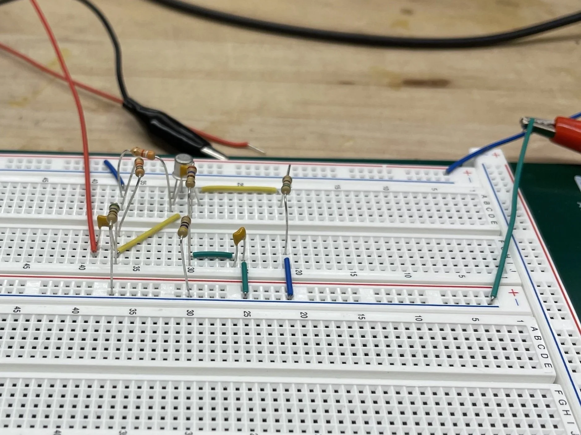
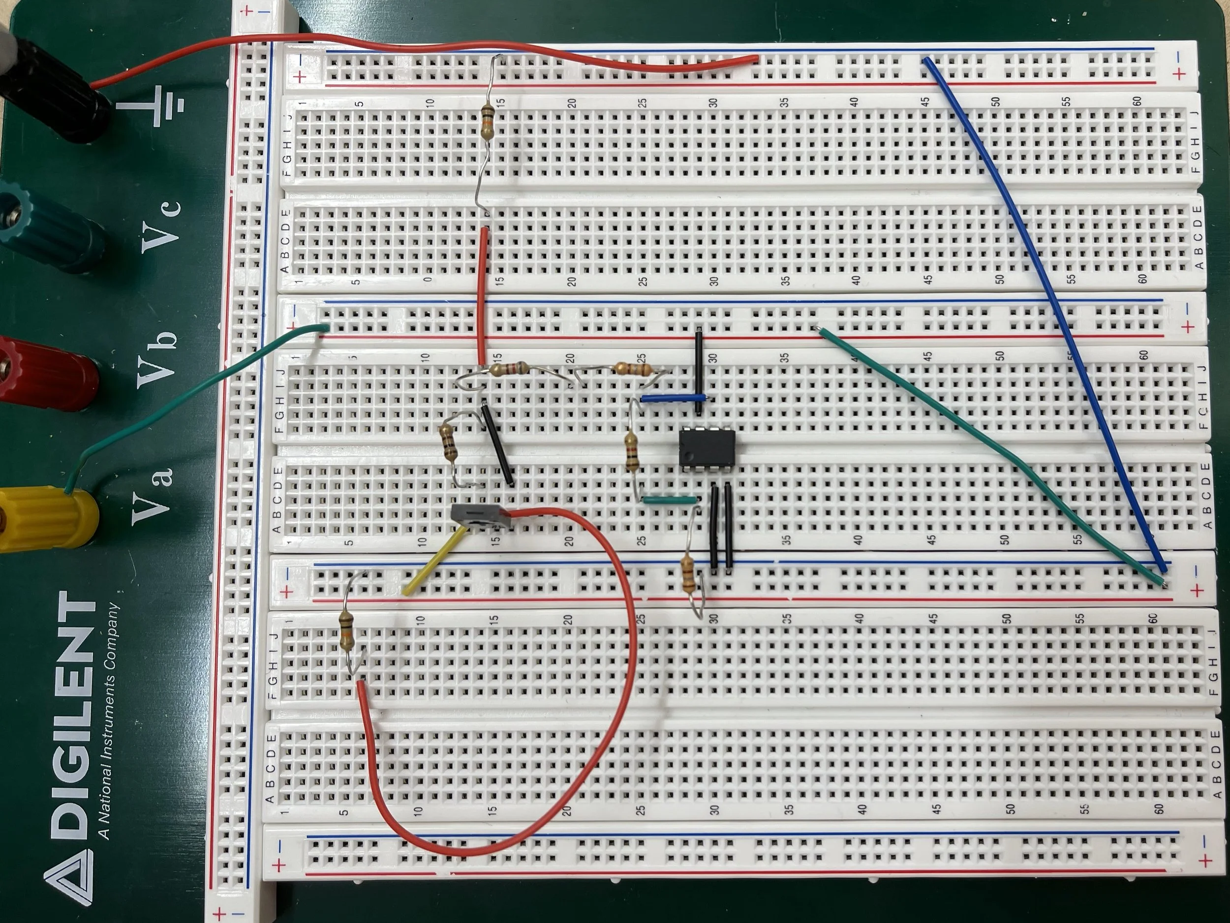
This project took me through the different aspects of designing an analog circuit. We started with coming up with a solution on paper and in SPICE simulation. Next, we moved to doing part selection. This part of the process was an interesting challenge because we had to make sure we were sourcing parts that could handle our expected current levels and operate properly at radio frequencies. Next came the breadboarding phase (pictured below) which allowed us to modify our design based on observations. Finally, we laid out, assembled, and tested a PCB for our design.